化工进展 ›› 2023, Vol. 42 ›› Issue (10): 5111-5120.DOI: 10.16085/j.issn.1000-6613.2022-2078

• 化工过程与装备 • 上一篇    下一篇

笼式调节阀的冲蚀磨损与空蚀

乔元1,2(), 仇畅3, 钱锦远3, 干瑞彬4, 徐春明1, 金志江3()   

  1. 1.中国石油大学(北京)化学工程与环境学院,北京 102249
    2.中国神华煤制油化工有限公司鄂尔多斯 煤制油分公司,内蒙古 鄂尔多斯 017200
    3.浙江大学化工机械研究所,浙江 杭州 310027
    4.中核苏阀科技实业股份有限公司,江苏 苏州 215129
  • 收稿日期:2022-11-07 修回日期:2023-02-06 出版日期:2023-10-15 发布日期:2023-11-11
  • 通讯作者: 金志江
  • 作者简介:乔元(1983—),男,博士研究生,研究方向为煤化工。E-mail:10511330@chnenergy.com.cn
  • 基金资助:
    国家自然科学基金(51875514)

Analysis of erosion and cavitation wear in the cage-typed control valve

QIAO Yuan1,2(), QIU Chang3, QIAN Jinyuan3, GAN Ruibin4, XU Chunming1, JIN Zhijiang3()   

  1. 1.School of Chemical Engineering and Environment, China University of Petroleum (Beijing), Beijing 102249, China
    2.Ordos Coal to Liquid Branch of China Shenhua Coal to Liquid Chemical Co. , Ltd. , Ordos 017200, Inner Mongolia, China
    3.Institute of Chemical Machinery, Zhejiang University, Hangzhou 310027, Zhejiang, China
    4.China Nuclear Suvalve Technology Industry Co. , Ltd. , Suzhou 215129, Jiangsu, China
  • Received:2022-11-07 Revised:2023-02-06 Online:2023-10-15 Published:2023-11-11
  • Contact: JIN Zhijiang

摘要:

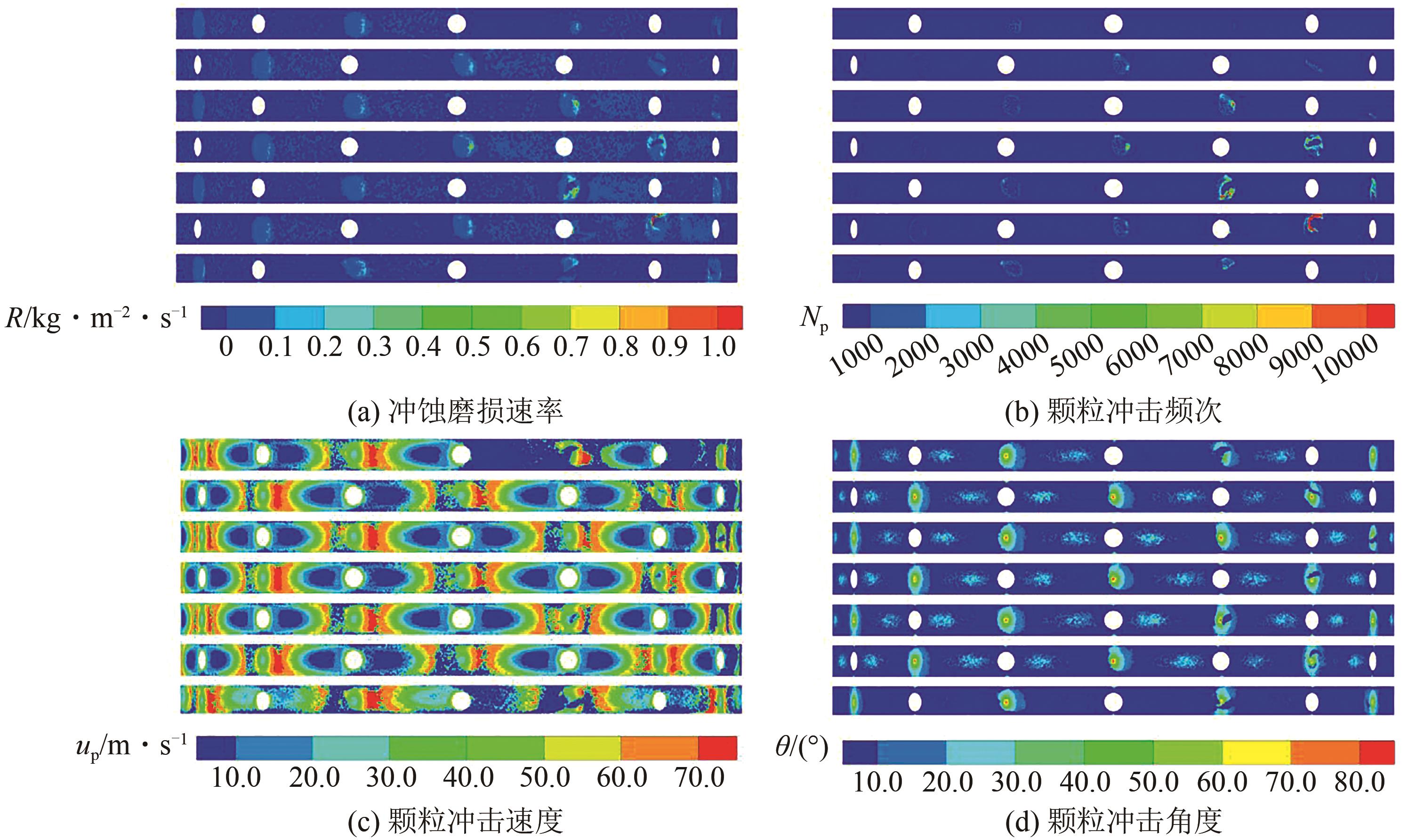
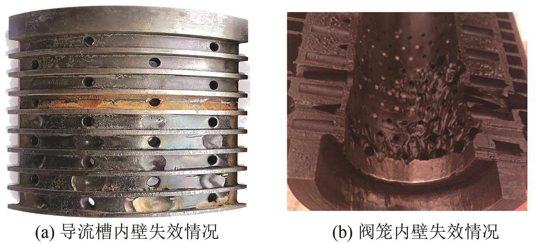
基于均质平衡流模型、空化模型和离散相模型,对煤直接液化工程中的笼式调节阀内气液固多相流动进行了仿真分析与预测,分析了阀内冲蚀磨损和空化空蚀的基本分布特征,并结合阀笼实际失效情况,验证分析结果并确定了阀笼失效的主要原因。结果表明:阀内空化发生的主要区域均位于阀笼的内层节流孔内。阀门入口压力不变时,随着阀门开度的增加,蒸汽相体积随之增加,流体流经的节流孔数增加,空化发生范围也随之增加,空蚀强度也随之增强;阀笼导流槽内壁受颗粒直接冲击中心及周围区域存在明显变形和穿透性缺陷,多个开度下冲蚀磨损速率最高的区域均位于导流槽内壁远离调节阀的进口侧;阀笼内壁内层节流孔出口周围的坑状缺陷主要是由于空化气泡破灭冲击壁面产生。

关键词: 笼式调节阀, 多相流, 冲蚀磨损, 空化, 失效分析

Abstract:

Based on the homogeneous equilibrium flow model, the cavitation model and the DPM model, the simulation and prediction of the gas-liquid-solid multiphase flow in the cage-typed control valve are carried out, and the distribution of erosion wear and cavitation in the valve is analyzed. Combined with the actual failure situation of the cage, the analysis results were verified and the main reason for the failure of the cage was determined. The results showed that the main areas of cavitation in the valve were located in the inner orifice of the valve cage. With the increase of the valve opening, the vapor volume increased, the number of orifices through which the fluid flows increased, the cavitation range and intensity also increased. Due to the high-speed impact of particles on the inner wall of the diversion groove, there were obvious deformation and penetration defects in the center and surrounding areas were directly impacted by the particles. The areas with the highest erosion wear rate under multiple openings were located on the inner wall of the guide groove away from the valve inlet side. The pit-like defects around the outlet of the orifice in the inner wall of the cage were mainly caused by the collapse of the cavitation bubbles and the impact on the wall.

Key words: cage-typed control valve, multiphase flow, erosion wear, cavitation, failure analysis

中图分类号: 

京ICP备12046843号-2;京公网安备 11010102001994号
版权所有 © 《化工进展》编辑部
地址:北京市东城区青年湖南街13号 邮编:100011
电子信箱:hgjz@cip.com.cn
本系统由北京玛格泰克科技发展有限公司设计开发 技术支持:support@magtech.com.cn